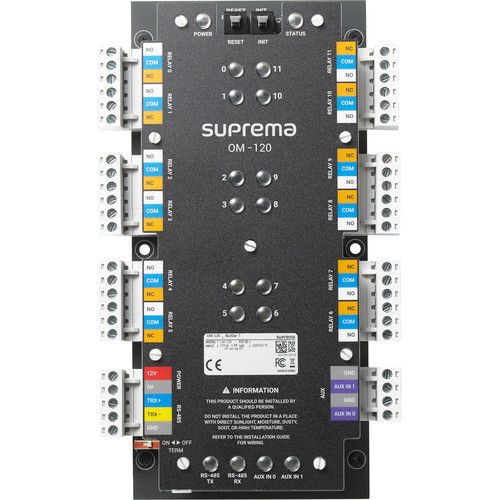
OM-120
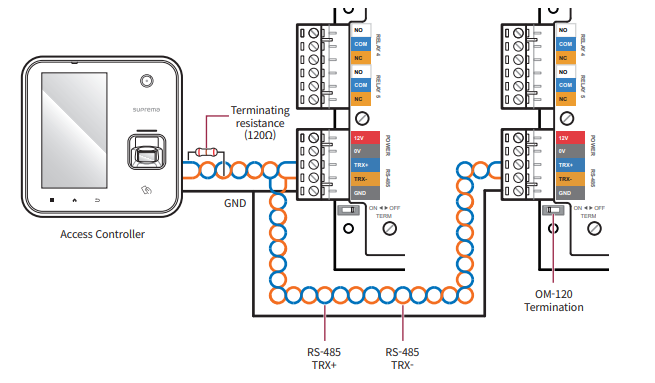
RS-485
RS-485 should be AWG24, twisted pair, and maximum length is 1.2 km.
Connect a termination resistor (120Ω) to both ends of a RS-485 daisy chain connection. It should be installed at both ends of the daisy chain. If it is installed in the middle of the chain, the performance in communicating will deteriorate because it reduces the signal level.
Up to 31 modules can be connected to the master device.
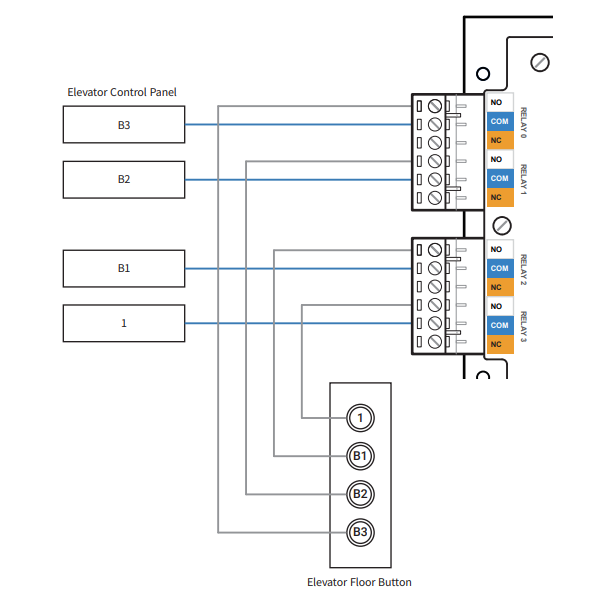
Relay 0
Relay connection may vary depending on the elevator. Please consult your elevator installer for details.
Each relay has to be connected to the corresponding floor.
Use the figure below as an example.
 1
1
Relay 1
Relay connection may vary depending on the elevator. Please consult your elevator installer for details.
Each relay has to be connected to the corresponding floor.
Use the figure below as an example.
1
Relay 2
Relay connection may vary depending on the elevator. Please consult your elevator installer for details.
Each relay has to be connected to the corresponding floor.
Use the figure below as an example.
1
Relay 3
Relay connection may vary depending on the elevator. Please consult your elevator installer for details.
Each relay has to be connected to the corresponding floor.
Use the figure below as an example.
1
Relay 4
Relay connection may vary depending on the elevator. Please consult your elevator installer for details.
Each relay has to be connected to the corresponding floor.
Use the figure below as an example.
1
Relay 5
Relay connection may vary depending on the elevator. Please consult your elevator installer for details.
Each relay has to be connected to the corresponding floor.
Use the figure below as an example.
1
Relay 6
Relay connection may vary depending on the elevator. Please consult your elevator installer for details.
Each relay has to be connected to the corresponding floor.
Use the figure below as an example.
1
Relay 7
Relay connection may vary depending on the elevator. Please consult your elevator installer for details.
Each relay has to be connected to the corresponding floor.
Use the figure below as an example.
1
Relay 8
Relay connection may vary depending on the elevator. Please consult your elevator installer for details.
Each relay has to be connected to the corresponding floor.
Use the figure below as an example.
1
Relay 9
Relay connection may vary depending on the elevator. Please consult your elevator installer for details.
Each relay has to be connected to the corresponding floor.
Use the figure below as an example.
1
Relay 10
Relay connection may vary depending on the elevator. Please consult your elevator installer for details.
Each relay has to be connected to the corresponding floor.
Use the figure below as an example.
1
Relay 11
Relay connection may vary depending on the elevator. Please consult your elevator installer for details.
Each relay has to be connected to the corresponding floor.
Use the figure below as an example.
1
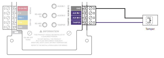
Auxiliary Port
Tamper Connection
If Input Module is detached from the installed location due to an external factor, it can trigger an alarm or save an event log.
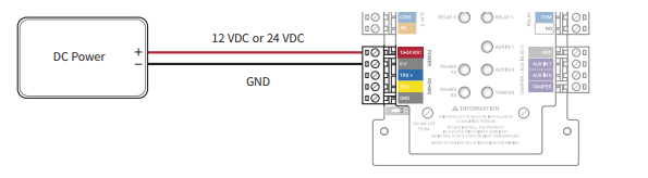
Power
Make sure to use separate power for the access control device and Input Module.
Use the correct power specifications (12 VDC, 130 mA or 24 VDC, 82 mA) Too much will short the device and too little can malfunction the device.
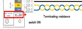
RS-485 Termination
In case that the RS-485 cable characteristic impedance is 120ohm, switch ON terminating resistance of IM-120 and install 120ohm terminating resistance to reader.
Reset and INIT
The INIT button is used to reset the connection of the Secure I/O from a previously connected device, it removes the certificates of the previous device back to factory.
The Reset button interrupts the power of the device, this stops you having to remove the power cable from the device to reboot it.
Device Info
Here is the information of the main device, you have some useful pieces of information:
- Model - This is the device itself and the version of the device
- Input - The power in put required for the device, If the device type has a P ODPB then it can also be powered over POE
- Serial number - This can be used for RMA's and to find the mac address of the Device
- The hardware revision of the Product
Power
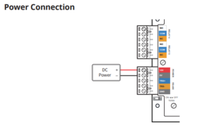
Power Connection Consists of a 12V 0.6A DC input The OM-120 requires 0.6 A and can it is recommended to connect an uninterruptible power supply to prevent power failure.