IM-120

Power
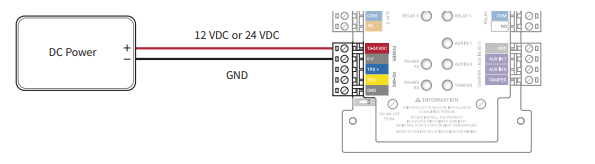
Make sure to use separate power for the access control device and Input Module.
Use the correct power specifications (12 VDC, 130 mA or 24 VDC, 82 mA) Too much will short the device and too little can malfunction the device.
RS-485
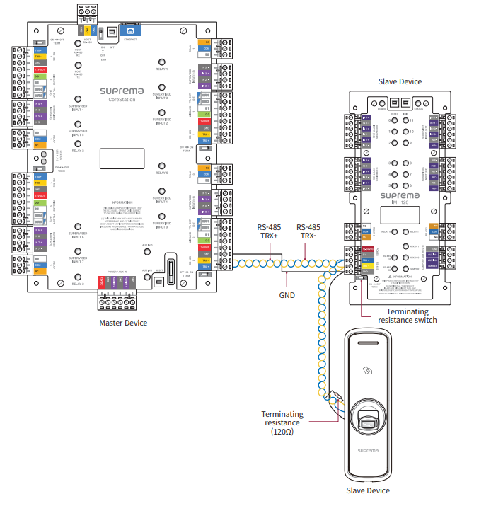
Use an AWG24 twisted pair with less than 1.2 km in length for the RS-485 cable.
If connecting with a RS-485 daisy chain, connect the termination resistor (120 Ω) to both ends of the daisy chain connection. If connected to the middle line, the signal level becomes smaller and the communication performance will deteriorate. Make sure to connect it to both ends of the daisy chain connection. Set the termination switch(TERM) to ON for Input Module.
Relay 0
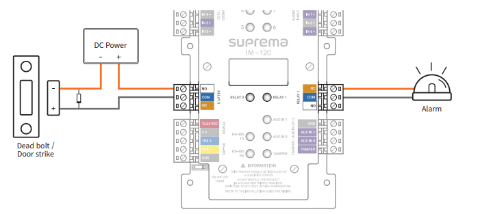
Relay Connection The relay of the Input Module can control door locks and alarms. Connect the relay as NC (Normally Closed) or NO (Normally Open) by referring to the installation guide of the connection device.
Relay 1
Relay Connection The relay of the Input Module can control door locks and alarms. Connect the relay as NC (Normally Closed) or NO (Normally Open) by referring to the installation guide of the connection device.
Inputs 0:2
You can connect a fire sensor, heat sensor, security sensor, door sensor, exit button, or etc. The SUPERVISED INPUT 0 to 11 pins detect the voltage flowing through the circuit to monitor device disconnection, short, on, and off conditions, and can also be used as a general TTL input. With BioStar 2, you can set the behavior according to the Supervised Input status, and you can monitor the status of each input.
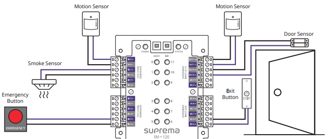
Inputs 3:5
You can connect a fire sensor, heat sensor, security sensor, door sensor, exit button, or etc. The SUPERVISED INPUT 0 to 11 pins detect the voltage flowing through the circuit to monitor device disconnection, short, on, and off conditions, and can also be used as a general TTL input. With BioStar 2, you can set the behavior according to the Supervised Input status, and you can monitor the status of each input.
Inputs 6:8
You can connect a fire sensor, heat sensor, security sensor, door sensor, exit button, or etc. The SUPERVISED INPUT 0 to 11 pins detect the voltage flowing through the circuit to monitor device disconnection, short, on, and off conditions, and can also be used as a general TTL input. With BioStar 2, you can set the behavior according to the Supervised Input status, and you can monitor the status of each input.
Inputs 9:11
You can connect a fire sensor, heat sensor, security sensor, door sensor, exit button, or etc. The SUPERVISED INPUT 0 to 11 pins detect the voltage flowing through the circuit to monitor device disconnection, short, on, and off conditions, and can also be used as a general TTL input. With BioStar 2, you can set the behavior according to the Supervised Input status, and you can monitor the status of each input.
Auxiliary connection
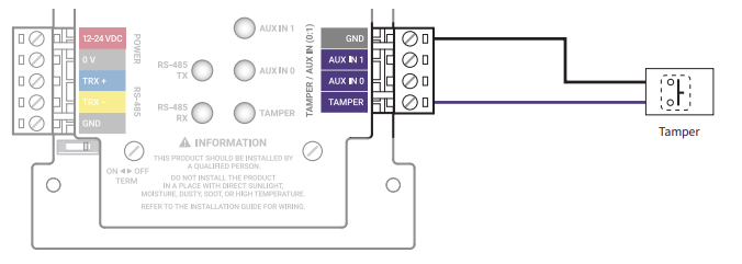
Tamper Connection
If Input Module is detached from the installed location due to an external factor, it can trigger an alarm or save an event log.
Reset
The Reset button interrupts the power of the device, this stops you having to remove the power cable from the device to reboot it.
Init
The init button is used to reset the connection of the Secure I/O from a previously connected device, it removes the certificates of the previous device back to factory.
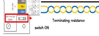
RS-485 Termination
In case that the RS-485 cable characteristic impedance is 120ohm, switch ON terminating resistance of IM-120 and install 120ohm terminating resistance to reader.