DI-24

Power
• Make sure to use separate power for the reader and Door Interface.
• Use the IEC/EN 62368-1 approved power adapter that supports higher power consumption than the product. If you wish to connect and use another device to the power supply adapter, you should use an adapter with a current capacity which is the same or larger than the total power consumption required for the terminal and another device. ‒ Refer to the Power in the product specifications for maximum current consumption specifications.
• DO NOT extend the length of power cable when using the power adapter.
Relay 0
Install a diode near both sides of the door lock wiring as shown in the figure to protect the relay from the
reverse current that occurs when the door lock operates. Make sure to connect the Cathode (direction to the
stripe) to the + part of the power while paying attention to the direction of the diode.
Only magnetic locks can be used when connecting the lock power directly.
Relay 2
Install a diode near both sides of the door lock wiring as shown in the figure to protect the relay from the
reverse current that occurs when the door lock operates. Make sure to connect the Cathode (direction to the
stripe) to the + part of the power while paying attention to the direction of the diode.
Only magnetic locks can be used when connecting the lock power directly.
Relay 1
Install a diode near both sides of the door lock wiring as shown in the figure to protect the relay from the
reverse current that occurs when the door lock operates. Make sure to connect the Cathode (direction to the
stripe) to the + part of the power while paying attention to the direction of the diode.
Only magnetic locks can be used when connecting the lock power directly.
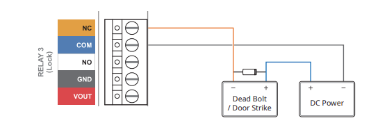
Relay 3
Install a diode near both sides of the door lock wiring as shown in the figure to protect the relay from the
reverse current that occurs when the door lock operates. Make sure to connect the Cathode (direction to the
stripe) to the + part of the power while paying attention to the direction of the diode.
Only magnetic locks can be used when connecting the lock power directly.
Power Out
Power Output 12 Vdc:
• Reader: Max. 0.6 A (0.3 A x 2)
• Lock: Max. 1.2 A (0.6 A x 2) 24 Vdc
• Reader: Max. 0.3 A (0.15 A x 2)
• Lock: Max. 0.6 A (0.3 A x 2)
Power Out
Power Output 12 Vdc:
• Reader: Max. 0.6 A (0.3 A x 2)
• Lock: Max. 1.2 A (0.6 A x 2) 24 Vdc
• Reader: Max. 0.3 A (0.15 A x 2)
• Lock: Max. 0.6 A (0.3 A x 2)
Power Out
Power Output 12 Vdc:
• Reader: Max. 0.6 A (0.3 A x 2)
• Lock: Max. 1.2 A (0.6 A x 2) 24 Vdc
• Reader: Max. 0.3 A (0.15 A x 2)
• Lock: Max. 0.6 A (0.3 A x 2)
Power Out
Power Output 12 Vdc:
• Reader: Max. 0.6 A (0.3 A x 2)
• Lock: Max. 1.2 A (0.6 A x 2) 24 Vdc
• Reader: Max. 0.3 A (0.15 A x 2)
• Lock: Max. 0.6 A (0.3 A x 2)
Output 0:2
The outputs are used to send signals to devices using time to live messages, these can range from alarms, sensors or input boards that need a controller.
Outputs can be set using the trigger and action function within Biostar or on the Device config
Output 3:5
The outputs are used to send signals to devices using time to live messages, these can range from alarms, sensors or input boards that need a controller.
Outputs can be set using the trigger and action function within Biostar or on the Device config
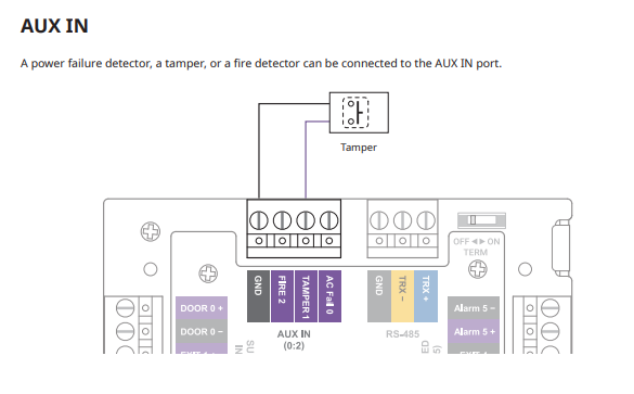
Aux In
Tamper Connection
A power failure detector, a tamper, or a fire detector can be connected to the AUX IN port.
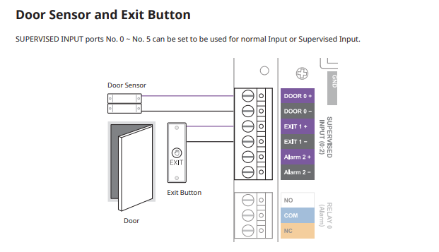
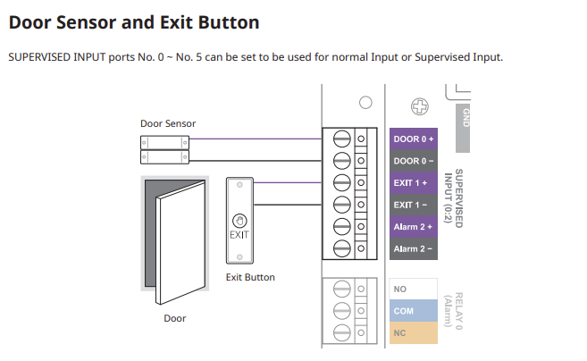
Supervised Inputs 0:2
SUPERVISED INPUT ports No. 0 ~ No. 5 can be set to be used for normal Input or Supervised Input.
The SUPERVISED INPUT Alarm port can be used by connecting 1 kΩ, 2.2 kΩ, 4.7 kΩ, or 10 kΩ resistors. After
connecting the resistor corresponding to the input device of the connection, set the same resistance value in
BioStar 2.
Supervised Inputs 3:5
SUPERVISED INPUT ports No. 0 ~ No. 5 can be set to be used for normal Input or Supervised Input.
The SUPERVISED INPUT Alarm port can be used by connecting 1 kΩ, 2.2 kΩ, 4.7 kΩ, or 10 kΩ resistors. After
connecting the resistor corresponding to the input device of the connection, set the same resistance value in
BioStar 2.
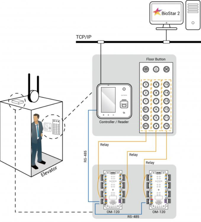
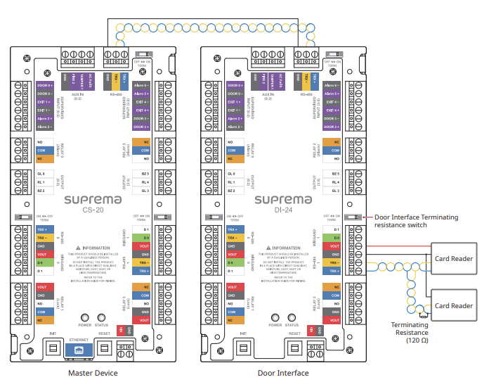
RS-485
The Door Interface supports three RS-485 ports, and by daisy-chaining multiple Door Interface units to the Master
Device, up to 34 doors can be configured.
RS-485 0
The Door Interface supports three RS-485 ports, and by daisy-chaining multiple Door Interface units to the Master
Device, up to 34 doors can be configured.
RS-485 1
The Door Interface supports three RS-485 ports, and by daisy-chaining multiple Door Interface units to the Master
Device, up to 34 doors can be configured.
Wiegand 0
Wiegand connections to the DI-24 can support multiple different formats.
They can be customized in Biostar 2 to accept various different bit lengths and authentication layers like Parity bits, Facility codes and more
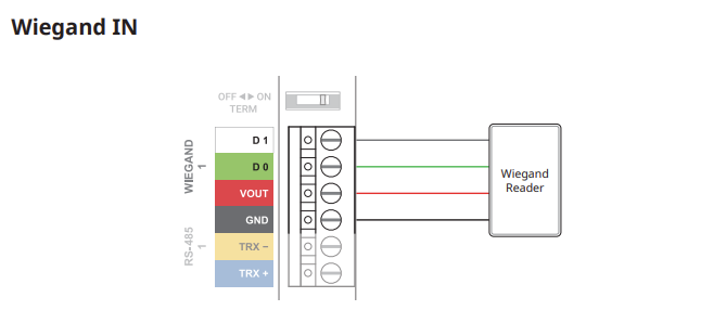
Wiegand 1
Wiegand connections to the DI-24 can support multiple different formats.
They can be customized in Biostar 2 to accept various different bit lengths and authentication layers like Parity bits, Facility codes and more
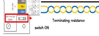
Termination Switch
In case that the RS-485 cable characteristic impedance is 120ohm, switch ON terminating resistance of DI-24 and install 120ohm terminating resistance to reader.
RS-485 Termination
In case that the RS-485 cable characteristic impedance is 120ohm, switch ON terminating resistance of IM-120 and install 120ohm terminating resistance to reader.
RS-485 Termination
In case that the RS-485 cable characteristic impedance is 120ohm, switch ON terminating resistance of IM-120 and install 120ohm terminating resistance to reader.