Corestation-40

Power
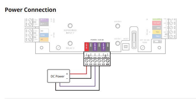
Power Connection Consists of a 12V 3A DC input The Corestation requires 1.5A and can emit 1.5A to external devices, it is recommended to connect an uninterruptible power supply to prevent power failure.
Supervised inputs port 2
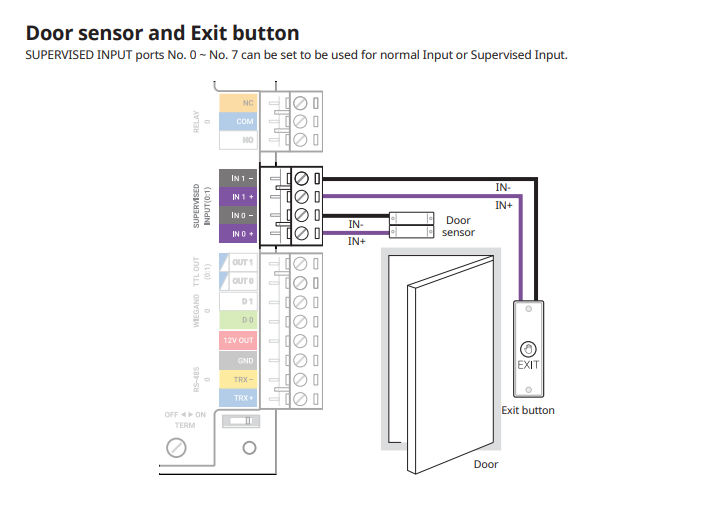
SUPERVISED INPUT terminals No. 7 can be set to be used for normal TTL input or supervised input.
Relay port 2
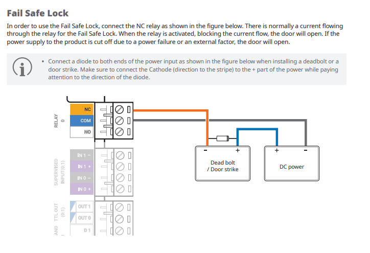
Connect a diode to both ends of the power input as shown in the figure below when installing a deadbolt or a door strike. Make sure to connect the Cathode (direction to the stripe) to the + part of the power while paying attention to the direction of the diode.
Ethernet
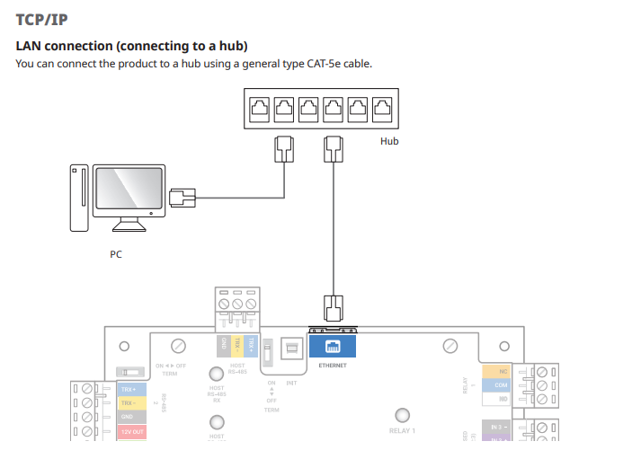
CS-40 has automatic MDI/MDI-X function, so it can be connected to a PC directly using a normal type CAT-5e cable.
Relay port 3
Connect a diode to both ends of the power input as shown in the figure below when installing a deadbolt or a door strike. Make sure to connect the Cathode (direction to the stripe) to the + part of the power while paying attention to the direction of the diode.
RS-485 port 3
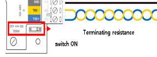
The number of RS-485 devices connected to CS-40 cannot exceed 64. Use an AWG24 twisted pair (Belden 9841) with a maximum length of 1.2 km for the RS-485 cable. Connect terminating resistance (120 Ω) to both ends of the RS-485 daisy chain connection. Make sure to connect it to both ends of the daisy chain connection. Set the termination switch(TERM) to ON for CS-40.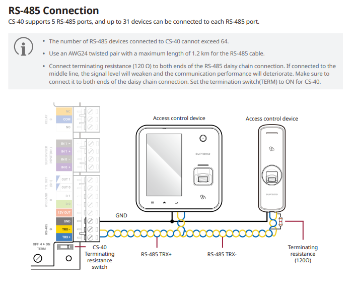
RS-485 port 1
The number of RS-485 devices connected to CS-40 cannot exceed 64. Use an AWG24 twisted pair (Belden 9841) with a maximum length of 1.2 km for the RS-485 cable. Connect terminating resistance (120 Ω) to both ends of the RS-485 daisy chain connection. Make sure to connect it to both ends of the daisy chain connection. Set the termination switch(TERM) to ON for CS-40.
RS-485 port 0
The number of RS-485 devices connected to CS-40 cannot exceed 64. Use an AWG24 twisted pair (Belden 9841) with a maximum length of 1.2 km for the RS-485 cable. Connect terminating resistance (120 Ω) to both ends of the RS-485 daisy chain connection. Make sure to connect it to both ends of the daisy chain connection. Set the termination switch(TERM) to ON for CS-40.
Wiegand port 1
The power output (12V, up to 1.5A) of CS-40 can be used as the power for a Wiegand device when CS-40 and the Wiegand device are connected. In other words, when 3 Wiegand devices that consume 200mA are connected, a device that consumes up to 900mA can be connected to the remaining power output terminal.

Wiegand port 3
The power output (12V, up to 1.5A) of CS-40 can be used as the power for a Wiegand device when CS-40 and the Wiegand device are connected. In other words, when 3 Wiegand devices that consume 200mA are connected, a device that consumes up to 900mA can be connected to the remaining power output terminal.
Wiegand port 0
The power output (12V, up to 1.5A) of CS-40 can be used as the power for a Wiegand device when CS-40 and the Wiegand device are connected. In other words, when 3 Wiegand devices that consume 200mA are connected, a device that consumes up to 900mA can be connected to the remaining power output terminal.
Relay port 1
Connect a diode to both ends of the power input as shown in the figure below when installing a deadbolt or a door strike. Make sure to connect the Cathode (direction to the stripe) to the + part of the power while paying attention to the direction of the diode.
Relay port 0
Connect a diode to both ends of the power input as shown in the figure below when installing a deadbolt or a door strike. Make sure to connect the Cathode (direction to the stripe) to the + part of the power while paying attention to the direction of the diode.
Wiegand port 2
The power output (12V, up to 1.5A) of CS-40 can be used as the power for a Wiegand device when CS-40 and the Wiegand device are connected. In other words, when 3 Wiegand devices that consume 200mA are connected, a device that consumes up to 900mA can be connected to the remaining power output terminal.
Supervised inputs port 3
SUPERVISED INPUT terminals No. 7 can be set to be used for normal TTL input or supervised input.
Supervised inputs port 1
SUPERVISED INPUT terminals No. 7 can be set to be used for normal TTL input or supervised input.
Supervised inputs port 0
SUPERVISED INPUT terminals 7 can be set to be used for normal TTL input or supervised input.
RS-485 port 2
The number of RS-485 devices connected to CS-40 cannot exceed 64. Use an AWG24 twisted pair (Belden 9841) with a maximum length of 1.2 km for the RS-485 cable. Connect terminating resistance (120 Ω) to both ends of the RS-485 daisy chain connection. Make sure to connect it to both ends of the daisy chain connection. Set the termination switch(TERM) to ON for CS-40.
RS-485 Termination
In case that the RS-485 cable characteristic impedance is 120ohm, switch ON terminating resistance of IM-120 and install 120ohm terminating resistance to reader.
RS-485 Termination
In case that the RS-485 cable characteristic impedance is 120ohm, switch ON terminating resistance of IM-120 and install 120ohm terminating resistance to reader.
RS-485 Termination
In case that the RS-485 cable characteristic impedance is 120ohm, switch ON terminating resistance of IM-120 and install 120ohm terminating resistance to reader.
RS-485 Termination
In case that the RS-485 cable characteristic impedance is 120ohm, switch ON terminating resistance of IM-120 and install 120ohm terminating resistance to reader.
Init
The init button is used to reset the connection of the Secure I/O from a previously connected device, it removes the certificates of the previous device back to factory.
Reset
The Reset button interrupts the power of the device, this stops you having to remove the power cable from the device to reboot it.
UL 294 Certification
Suprema have received the UL 294 certification for the Corestation

Outputs 4:5
The outputs are used to send signals to devices using time to live messages, these can range from alarms, sensors or input boards that need a controller.
Outputs can be set using the trigger and action function within Biostar or on the Device config
Outputs 2:3
The outputs are used to send signals to devices using time to live messages, these can range from alarms, sensors or input boards that need a controller.
Outputs can be set using the trigger and action function within Biostar or on the Device config
Outputs 6:7
The outputs are used to send signals to devices using time to live messages, these can range from alarms, sensors or input boards that need a controller.
Outputs can be set using the trigger and action function within Biostar or on the Device config
Outputs 0:1
The outputs are used to send signals to devices using time to live messages, these can range from alarms, sensors or input boards that need a controller.
Outputs can be set using the trigger and action function within Biostar or on the Device config
RTC Battery
The RTC Battery is used for the real time clock of the device, this is important for the scheduling of events or access times in a centralized system.
RTC Battery can be replaced unlike most devices.
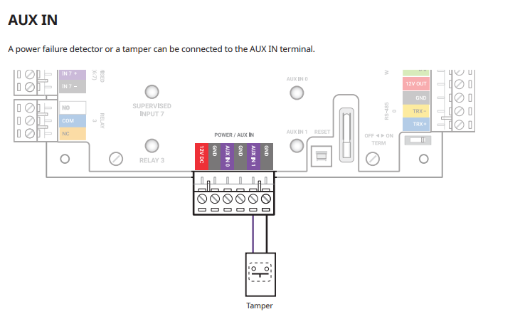
Auxiliary Port
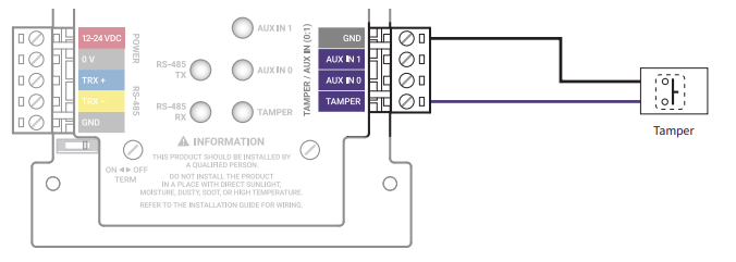
Tamper Connection
If Input Module is detached from the installed location due to an external factor, it can trigger an alarm or save an event log.
Auxiliary
Tamper Connection
If Input Module is detached from the installed location due to an external factor, it can trigger an alarm or save an event log.
RS-485 Host
The number of RS-485 devices connected to CS-40 cannot exceed 64. Use an AWG24 twisted pair (Belden 9841) with a maximum length of 1.2 km for the RS-485 cable. Connect terminating resistance (120 Ω) to both ends of the RS-485 daisy chain connection. Make sure to connect it to both ends of the daisy chain connection. Set the termination switch(TERM) to ON for CS-40.
Serial Number
Here is the information of the main device, you have some useful pieces of information:
- Model - This is the device itself and the version of the device
- Input - The power in put required for the device, If the device type has a P ODPB then it can also be powered over POE
- Serial number - This can be used for RMA's and to find the mac address of the Device
- The hardware revision of the Product