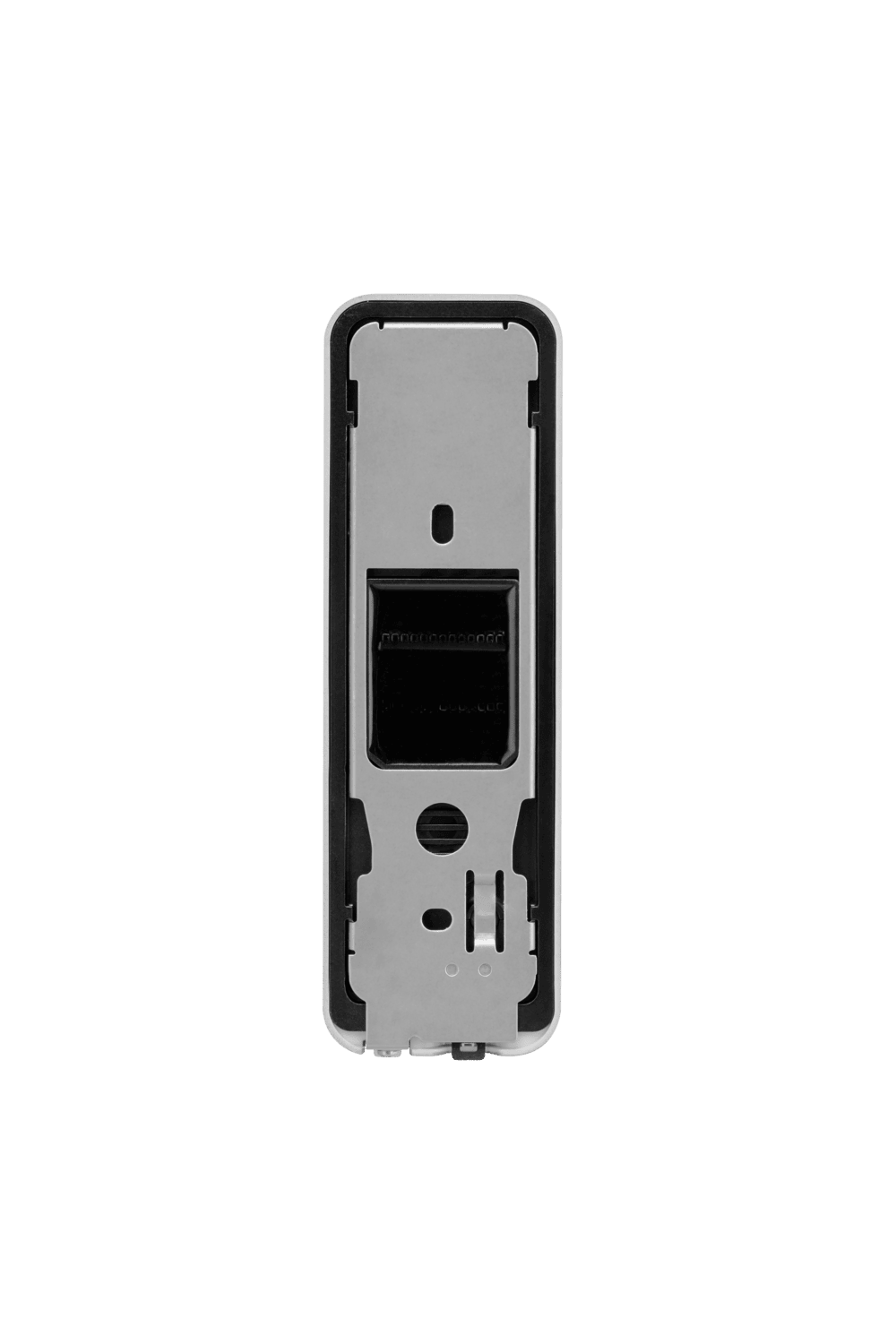
BioEntry W3 Back
BioEntry W3 Cables 1-7
Pin Layout 1 - 7
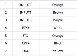
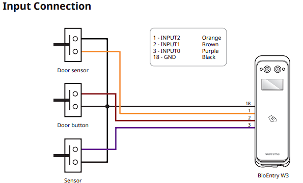
Input Connections, this is used for sending input from Push to exit buttons, camera inputs or door sensors
Pins 4 - 7 is the Ethernet layout for the device.
Below is the setup

BioEntry W3 Pins 8-13
Pin 8 - 13
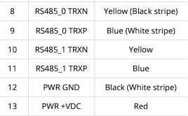
Pin 8 & 9 are apart of the RS-485 setup for slave units or OSDP
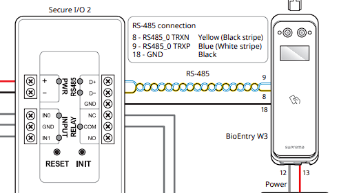
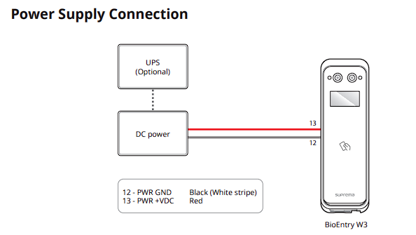
Pins 12 & 13 are the Power connections of the W3 reader, this takes 12v DC @ 1Amp
BioEntry W3 Pins 14-20
Pins Layout:
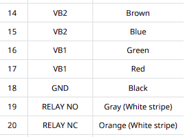
Pin 18 is the ground of the device. This can be used for the Input connection.
Pins 19-21 is the Relay of the device. This can be used to open doors or secure locks from the relay directly
The max load of the device relay is 2Amps
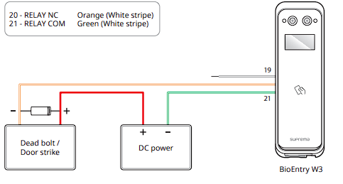
BioEntry W3 Pins 21-26
Pin layout:
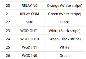
Pins 21 & 22 is apart of the Relay . This can be used to open doors or secure locks from the relay directly
The max load of the device relay is 2 Amps
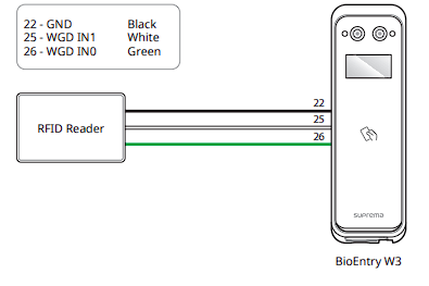
Pins 23 - 26 is the Wiegand of the reader. This is an import part of the device that can help integrate the device on to 3rd party systems. This mainly includes Net2, Lenel, Mercury and more.
This also allows external Wiegand readers to be added to the BEW3 for wiegand inputs. For example HID readers.
Pins 23 & 24 offer Wiegand input, Pins 25 & 26 allow Wiegand output both can be used at the same time
Reset Button
On the back of the device is a reset button located at the bottom left of the reader.
This button, much like the W2 and Xpass 2 readers can be used to either factory default the unit or reset the network back to DHCP
This button is useful in situations when the information of the device is completely lost